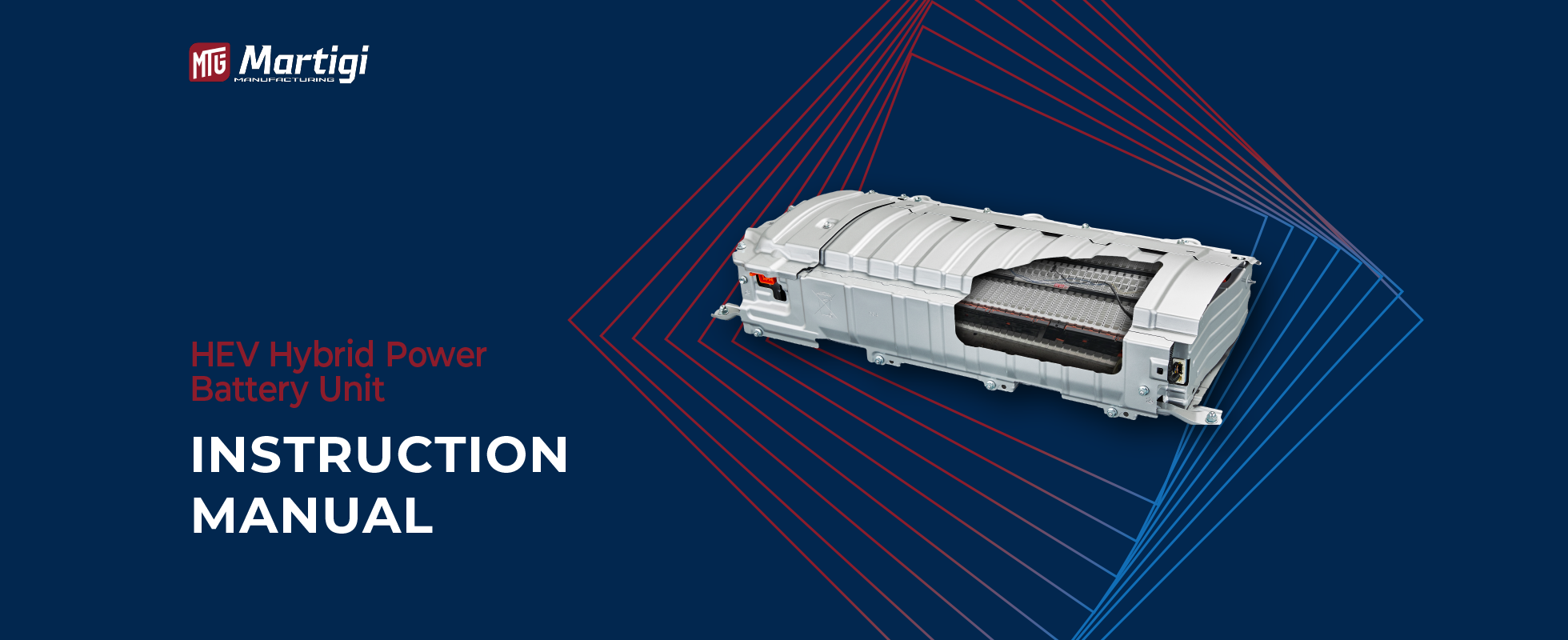
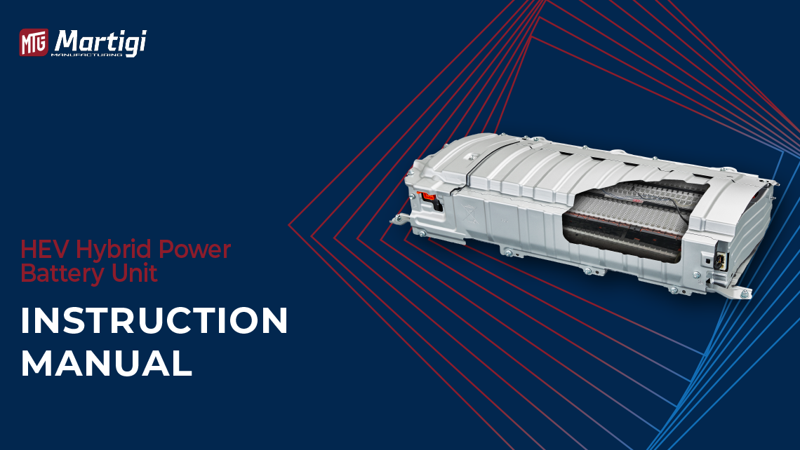
Thank you for choosing our company’s NCM series power battery cell products
The NCM high-power cell unit adopts an aluminum substrate with better heat conductivity, combined with a silicon sheet with high thermal conductivity, demonstrating its remarkable advantages. The high power characteristics of NCM and the high energy characteristics of lithium-ion batteries. Optimizing materials and electrochemical systems, using full-pole-ear laser welding technology, achieves ultra-low internal resistance, extremely high reliability, and a safe thermal management structural design; based on the external characteristics of the linear charge-discharge curve, the SOC and charging control management are very accurate. By adjusting the surface capacity and N/P ratio, optimizing the positive and negative electrode potentials, avoiding negative lithium precipitation, the cell is inherently safer during charging and discharging. It is widely used in power transmission, kinetic energy recovery, 12/24V emergency start, 48V mild hybrid MHEV, high-voltage HEV, FCEV, and other vehicle markets
Product Model: NCM21278128
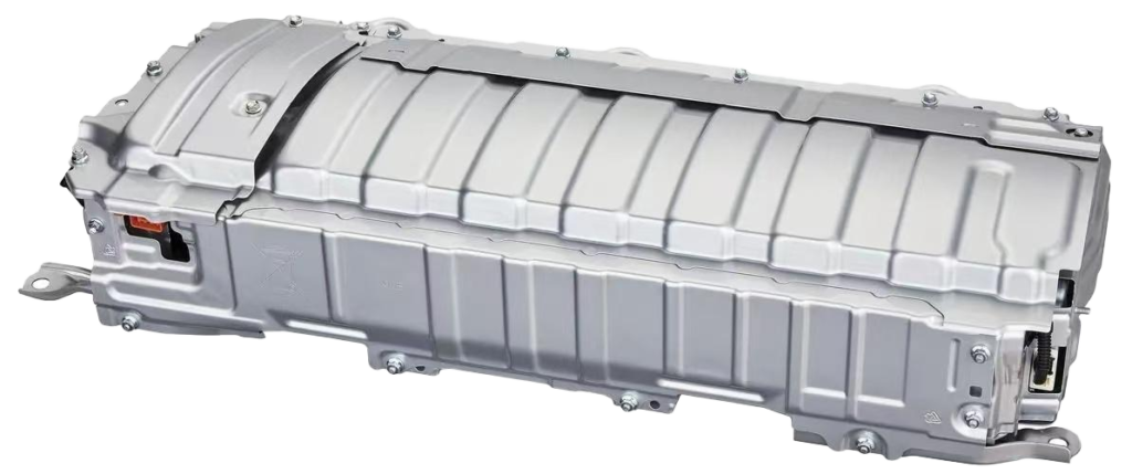
Sample diagram

Product model naming rule
NCM indicates that the cathode material system is the NiCoMn nickel-cobalt-manganese ternary composite material.
21278128 represents the main outline dimensions of the battery cell unit
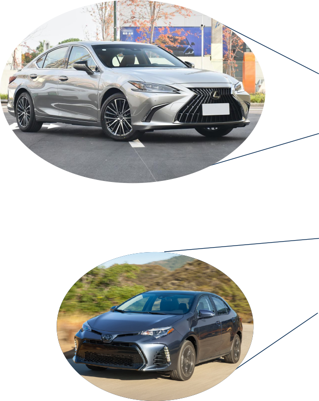
Applicable Vehicle Models |
Quantity per Vehicle |
Weight |
|---|---|---|
Toyota Prius (2nd & 3rd Gen, 2004-2011) | 28 slices/vehicle | 28.5 kg |
Prius C / Aqua | 20 slices/vehicle | 20.2 kg |
Toyota Corolla | 28 slices/vehicle | 28.5 kg |
Toyota Levin | 28 slices/vehicle | 28.5 kg |
Lexus CT200h | 28 slices/vehicle | 28.5 kg |
Toyota Camry XV40 (6th Gen, 2007-2011) | 34 slices/vehicle | 34.5 kg |
Toyota Camry XV50 (7th Gen, 2012-2016) | 34 slices/vehicle | 34.5 kg |
Lexus ES300h | 34 slices/vehicle | 34.5 kg |
Lexus GS450h | 40 slices/vehicle | 40.5 kg |
Lexus IS300h | 32 slices/vehicle | 32.5 kg |


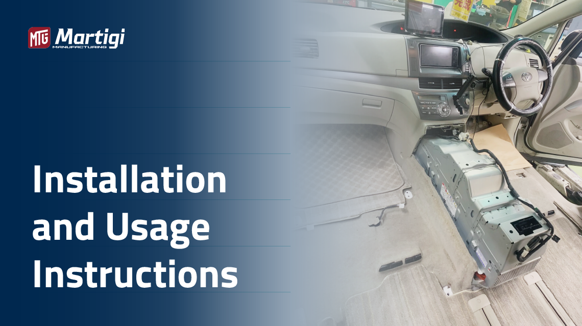
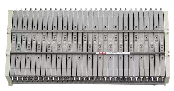
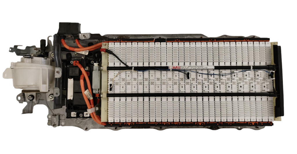
Step 1:
Remove the original vehicle battery pack assembly as shown
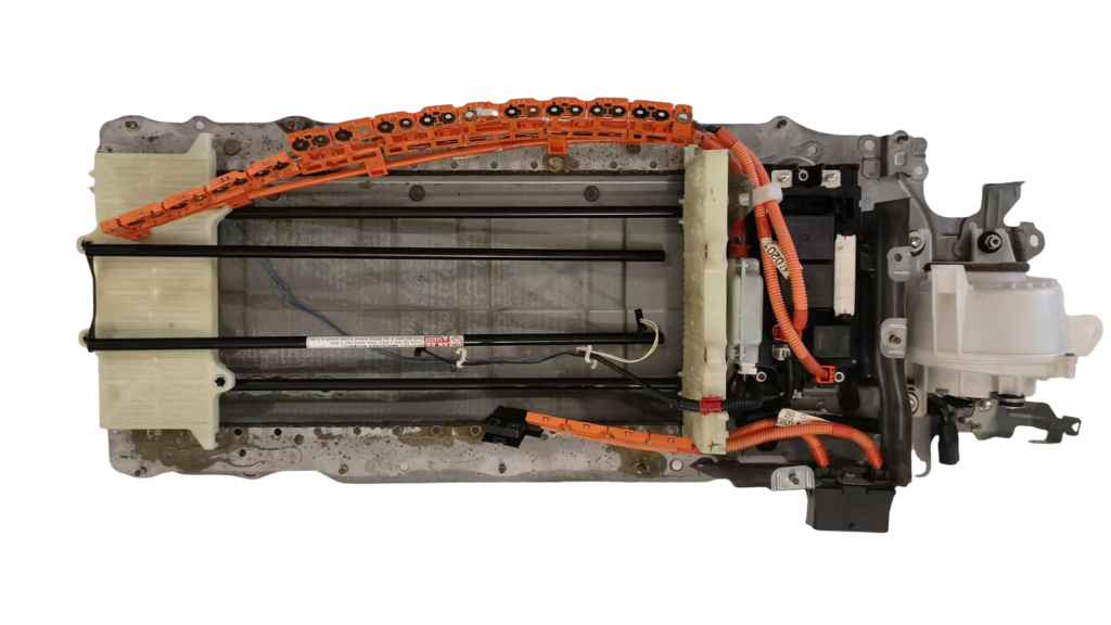
Step 2:
Removing the casing exposes battery cells, showcasing internal structure and safety protocols
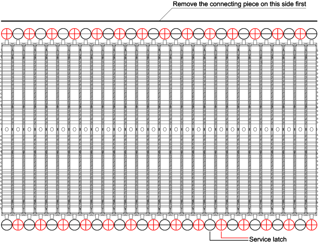
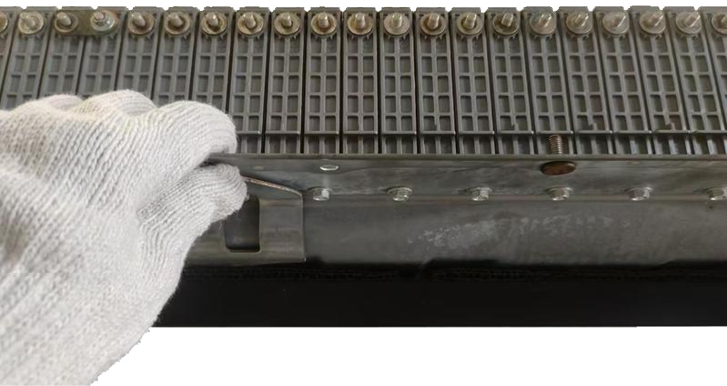
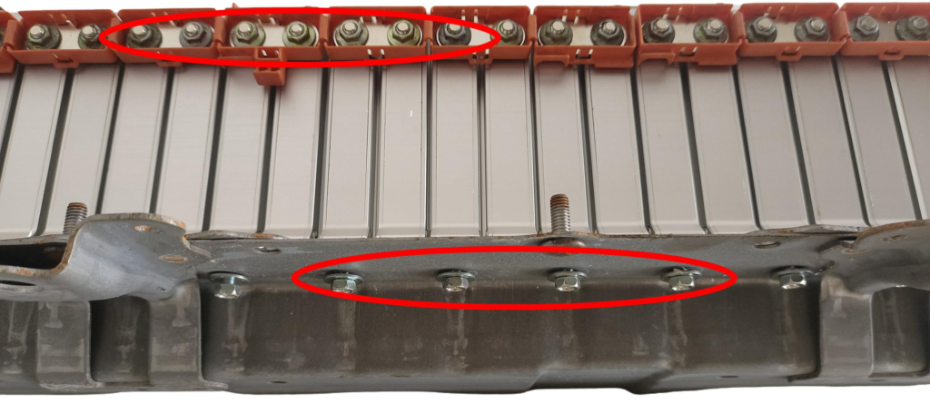
Step 3:
First, remove the bus bar shunt and the bottom fixing screws of the battery cells as shown in the figure.
Step 4:
After completing the above steps, start measuring the voltage of the NCM battery cells. Be careful to avoid short circuits caused by the contact of the terminals with the metal conductor or the measurement probe touching the outer shell of the battery cell. The voltage difference between all battery cells should be within 50mV before proceeding to replace and install the new battery cells. If the voltage difference exceeds this value, please contact the local dealer immediately for replacement.
Step 5:
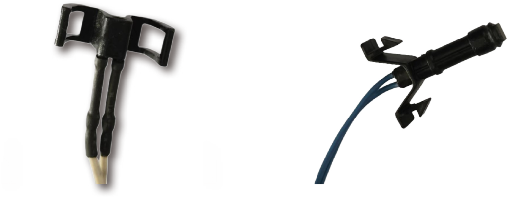
According to the arrangement form of the battery cells, restore the installation to the initial arrangement state. The electrode posts of the battery cells are made of copper, which has better electrical conductivity.According to the arrangement form of the battery cells, restore the installation to the initial arrangement state. The electrode posts of the battery cells are made of copper, which has better electrical conductivity, but the material is relatively softer than iron. Therefore, it is necessary to pay attention to the installation torque of the flow guide plate, which is approximately 25-28 Kgf·cm (2.5-2.8 N·m). At the same time, it is also necessary to gradually lock the fixing screws under the battery step by step. Avoid tightening all at once. Instead, install the flow guide plate first (do not tighten yet), then screw the bottom screw to about 60%, slightly shake the entire battery module, until the flow guide plate is fully in contact without external stress, and then repeat tightening several times in an up-and-down manner until it is fully tightened. The wiring assembly is fixed with cable ties. The temperature probe may vary slightly depending on the vehicle model. It can also be installed back to the original position as is
Step 6:
After all the installations are completed and checked, the enclosure can be sealed to be ready
Vehicle Model Compatibility Table
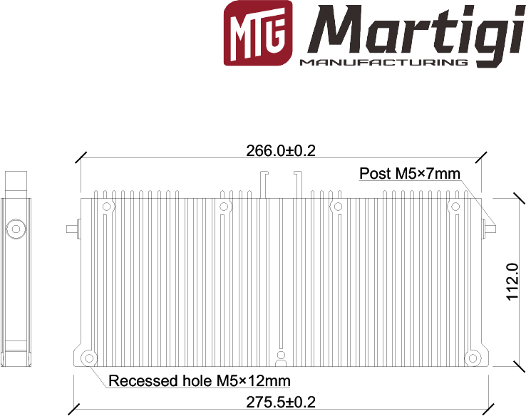
Item |
Basic Parameters |
Remarks |
|---|---|---|
Length (L) | 278 mm | Excludes terminal posts |
Width (W) | 21 mm | |
Height (H) | 128 mm | |
Red Terminal Post | Positive (+) post | |
Black Terminal Post | Negative (–) post | |
Weight | 1030g ± 15g | |
Casing Material | AL 6061 aluminum alloy | T6 heat-treatment + anodized |
Terminal Post Mounting Size | M5 × 7 mm H 59 brass | Metric thread pitch 0.8 mm |
Battery-Cell Bottom Fixing Hole Size | M5 × 12 mm | Metric thread pitch 0.8 mm |
Electrical performance indicators of battery cells
Item |
Basic Parameters |
Remarks |
|---|---|---|
Nominal Capacity | 6.0 Ah | 1 C, 25 ± 2 °C, 5.60–8.40 V |
Initial Impedance | < 2.4 mΩ | AC, 1 kHz, 50 % SOC |
Điện áp định mức | 7.2 V | |
Charge Cut-off Voltage | 8.4 V | CC/CV, charge cut-off current 0.01 C |
Điện áp cắt đứt khi xả | 5.6 V | |
Cycle Life | 3000 cycles | 25 °C, 80 % Depth of Discharge, remaining capacity ≥ 80 % |
perating Temperature Range | –25 °C to 65 °C | |
Maximum Continuous Discharge Current | 59 A | |
Peak Output Power | 1062 W @ 10 s | Measured at 50 % SOC |
Peak Input Power | 740 W @ 10 s | Measured at 50 % SOC |
Delivery Voltage | 7.25–7.40 V | |
Delivery State of Charge | 50 % | |
Enclosure Material | AL 6061 | T6 heat-treated + anodized |
Shell Center Temperature During Cell Charge | 45 °C ± 2 °C | Test conditions: ambient 25 °C ± 2 °C; cell at 100 % SOC, 8.4 V; charged at 10 V/5 A constant current for 4 minutes; temperature measured at center of both housing sides. |
Electrical performance indicators of battery cells
Electrocell charging curve diagram
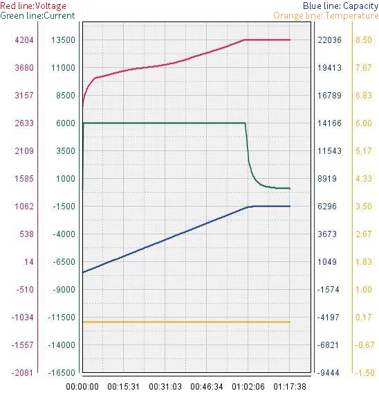
1C charging curve, which means charging to a voltage of 4.20V with a current of 6A. The red line represents voltage, the green line represents current, and the blue line represents capacity
Electrocell discharge curve diagram
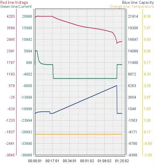
1C discharge curve graph, that is, discharging at a current of 6A until the voltage reaches 2.80V. Red represents voltage, green represents current, and blue represents capacity
BMS sample diagram

BMS Basic Performance Indicator Parameters
Item |
Typical Value |
Remarks |
|---|---|---|
Over-charge monitoring voltage | 4.200 ± 0.025 V | |
Over-charge release voltage | 4.190 ± 0.035 V | |
Over-charge monitoring delay time | 250 m | |
On-state (conductance) resistance | 0.9 ± 0.1 Ω | |
Continuous over-charge current capacity | 5 A | Long-term duty |
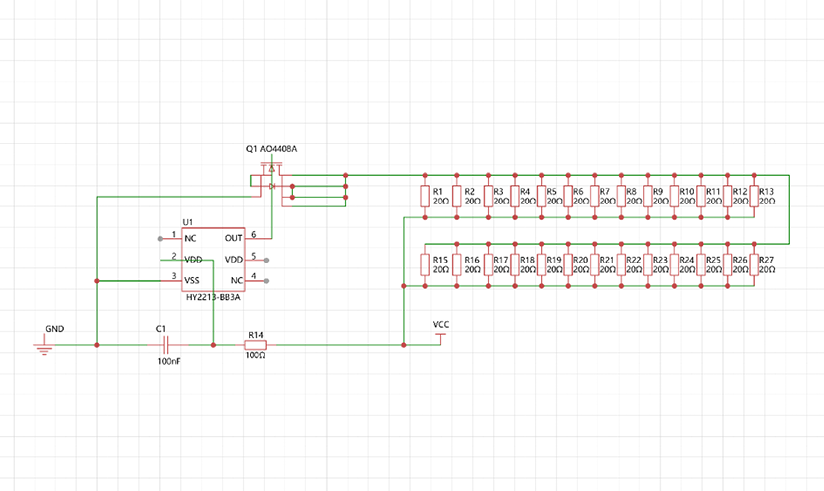
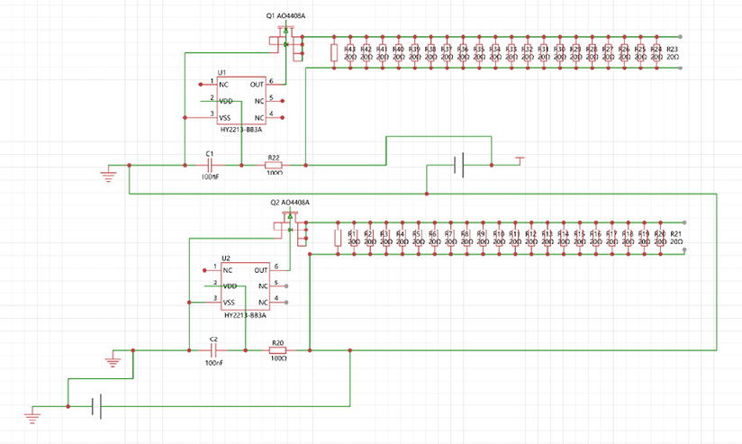
BMS Circuit Diagram
Battery cell assembly schematic diagram
Safety Warning
| Do not put the battery into fire or heat it in any other way |
| Do not short-circuit or install it with incorrect polarity.Avoid mechanical damage or abusea |
| Do not short-circuit or install it with incorrect polarity.Avoid mechanical damage or abuse |
| Do not mix batteries from different manufacturers or of different models |
| Do not disassemble or modify the external structure of the battery. Do not strike or puncture the battery with external force |
| Do not put the battery into water, seawater, strong acidic, or strong alkaline substances |
| Avoid direct sunlight exposure and avoid high temperature and high humidity (temperature ≤ 60, humidity ≤ 95%) |
| When operating the battery, wear rubber or rubber gloves |
| When charging or discharging the battery, ensure that the battery has voltage, current, temperature monitoring and protection |
| If there is leakage, smoke or damage to the battery, immediately stop using it and contact the after-sales customer service for handling |